This product is a DC continuous wired dual-mode communication version of digital intelligent DC power supply system, is a high-performance DC power supply independently developed by Jiangsu Esilang Electric Co., LTD., with the characteristics of simple operation, high stability, high reliability, the power system can be multiple parallel, to achieve power expansion to meet higher power requirements, but also with wired communication. Wireless communication redundancy. With our host computer software can achieve equipment control, parameter configuration, user management, data log export and other functions, is used for laser semiconductor, high-power LED lighting, power device aging, motor testing and other equipment need long-term stable DC power supply places the best choice.
Use environment
item | unit | Minimum value | Typical value | Maximum value | remark |
Operating temperature | ℃ | - 10 | + 25 | + 50 |
|
Storage temperature | ℃ | - 40 | + 25 | + 70 |
|
Relative humidity | % | 5 | / | 95 | non-condensing |
altitude | m |
| 0 | 2800 | When the capacity exceeds 1000 MB, the capacity should be reduced according to GB/T 3859.2. The system works properly and meets the derating requirements of GB3859.2-2013 |
Heat dissipation mode | / | Conduction of liquid cooling heat dissipation, specifically through the base plate at the bottom of the module (the flatness of the bottom plate is ≤0.25mm) through good thermal conductivity materials affixed to the platform with liquid cooling measures to dissipate heat, liquid flow ≥10L/min, inlet temperature ≤28℃ |
Operating environment | The working environment should be free from conductive explosive dust, and should be free from corrosive metals and damaging insulation gases and vapors |
Electrical characteristic
3.1 Input Features
item | unit | Minimum value | Typical value | Maximum value | remark |
Rated input voltage range | Vac | 330 | 380 | 450 | / |
Ac input voltage frequency | Hz | / | 50/60 | / | / |
Power factor | / | 0.99 or higher | Rated input and load |
Input current | A | / | / | 38 | Low voltage input, full output |
Input impulse current | A | / | / | 60 | 480V input, output rated load. |
Ac input system | Power AC input: 380Vac | Wiring sequence: First connect the signal AC, then connect the power AC, power AC input and signal AC are connected, the power system can work |
Signal AC input: 220Vac |
3.2 Output Features
Serial number | item | Parameter value | unit | remark |
1 | Output power | 20000 | W | Maximum value |
2 | Output voltage range | 123-133. | Vdc | Follow the output pump voltage changes |
3 | Output current | 45 * 3 | A | Single current maximum 45A, can be adjusted differentially, can also be adjusted synchronously, specific consult the manufacturer |
4 | Conversion efficiency | P 90 | % | Rated input and load |
5 | Current ripple | 4 or less | % | / |
6 | Output rise time | 22 or less | uS | Output current from 10% to 90%@ Output voltage 140V, output rated current |
3.3 Protection Features
Serial number | generic | content | Parameter value | unit | remark |
1 | input | Undervoltage protection | < 280 | V | Under voltage protection, self-recovery after the fault is removed |
2 | Overvoltage protection | > 540 | V | Overvoltage protection, self-recovery after the fault is removed |
3 | Phase loss protection | There are | When any phase protection is missing, it can recover after the fault is removed |
4 | Overcurrent protection | There are | AC AC input fuse protection |
5 | exportation | Current limiting protection | > 56 | A | If the single output current exceeds this value, the output is automatically turned off and locked |
6 | Limited power protection | > 21000 | W | When the load exceeds the limit, it enters the power limit protection and can be restored after the load is removed |
7 | logic | Temperature protection | 24 | Road, | Temperature protection point of each channel can be set |
8 | Water pressure protection | 1 | Road, | On-off detection |
9 | Water cooler interlock protection | 1 | Road, | On-off detection |
10 | PD light leakage protection | 6 | Road, | Each PD protection point can be set |
11 | QBH fiber output device protection | 1 | Road, | On-off detection |
4. Monitoring and alarm functions and interfaces
4.1 Indicator Definition
Serial number | generic | item | Parameter value | Status/Description | remark |
1 | Pilot lamp | Power | red | Power Supply AC input NG | The color of the lamp can be customized |
green | Power AC input OK | The color of the lamp can be customized |
2 | Pilot lamp | Active | red | The laser is not turned on, or the laser current is < 2A | The color of the lamp can be customized |
green | Turn on laser and current ≥2A | The color of the lamp can be customized |
3 | Pilot lamp | Alarm | red | Temperature detection, PD detection, QBH detection, water pressure detection, water cooler detection of any of the above NG | See Fault Error Code Table The color of the lamp can be customized |
green | Temperature detection, PD detection, QBH detection, water pressure detection, water cooler detection are OK |
yellow | The temperature reaches the alarm temperature. Procedure |
4.2 Interface Definition
4.2.1 Power terminal Interface
Serial number | port | definition | Instructions | remark |
1 | input | L1 | Ac input L1 | Three-phase AC input |
L2 | Ac input L2 |
L3 | Ac input L3 |
PE | Grounded PE |
2 | exportation | Vo1 | Dc output (45A) | DC1 output |
Vo2 | Dc output (45A) | DC2 output |
Vo3 | Dc output (45A) | DC3 output |
4.2.2 Expanding terminal interfaces
Serial number | Interface type | Interface definition | Foot definition | Instructions |
1 | Net interface | ETH | RJ45 | 100 megabit network port |
2 | 2*3P | RS232 | 1 | RS232_TX |
2 | RS232_TX |
3 & 4 | ISO_GND |
3 | RS485 | 5 | RS485_A |
6 | RS485_B |
4 | 2*8P | Group one temperature | 1-16 | T1-T8 |
5 | 2*8P | Group two temperature | 1-16 | T9-T16 |
6 | 2*8P | Group three temperature | 1-16 | T17-T24 |
7 | 2*6P | PD | 1-12 | PD1-PD6 |
8 | 2*3P | QBH | 1 & 2 | QBH on-off detection |
9 | Water pressure detection | 3 & 4 | Water pressure on-off test |
10 | Water cooler interlock | 5 & 6 | Water cooler interlock detection |
11 | 2*2P | Manul_CTRL | 1-4 | External control mode detection |
12 | 2*5P | Panel light | 1 & 2 & 10 | +12V |
3 & 5 | POWER status indication |
7 & 9 | ACTIVE status indication |
4 & 6 | ALARM status indication |
13 | 2P | Indicator light | 2 | Indicates that the optical interface is positive |
1 | Indicates that the optical interface is negative |
14 | 2P | DC power input | 2 | DC24V power supply positive |
1 | DC24V power supply is negative |
15 | 3P | AC power input | 3 | AC power supply L |
2 | AC power supply N |
1 | AC Power PE |
5. Laser power system - signal control
5.1 Modulation Mode
Serial number | Modulation mode | Instructions | Communication mode |
1 | Analog modulation | The analog quantity is linearly related to the output current | ETH/RS232 CLI command |
2 | Digital modulation | Frequency modulation range: 0.01KHZ-5KHZ Duty cycle 50% | ETH/RS232 CLI command |
5.2 Definition of peripheral sensing parameters
Serial number | category | item | quantity | unit | Reserve note |
1 | Temperature detection | NTC | T1-8/ T9-T16/ T17-T24 | 1 | meter | Line length can be customized |
2 | PD light leakage detection | PD | PD1-PD6 | 0.2 | meter | Line length can be customized |
3 | QBH detection | On-off intelligent detection | 1 | a | Suitable for 20 meters |
4 | Water pressure detection | Water pressure intelligent detection | 1 | a | Suitable for 20 meters |
5 | Water cooler inspection | Water cooling can detect | 1 | a | Suitable for 20 meters |
5.3 Timing Control Diagram

6. Laser power supply system - electrical control 6.1 Electrical schematic diagram: When controlling the AC220V contactor coil:
Figure 1
When controlling the DC24V contactor coil:

Figure 2
6.2 Electrical symbols and parameters
Serial number | Identification symbol | item | Model/Parameter | quantity | unit | remark |
1 | KM1/KM2 | AC220V coil control type contactor | 1 Normally open contact, coil voltage 220Vac | 2 | a | See Figure 1 for AC220V control and Figure 2 for DC24V control |
DC24V coil control type contactor | 1 Normally open contact, coil voltage 24Vdc |
2 | PWR_Key | Permission switch | Key switch, ON/OFF | 1 | a | ON/OFF |
3 | ACT_BTN | Power-on switch | Self-resetting push-button switch | 1 | a | Self-resetting type |
4 | E-STOP | Scram button | Self-locking type | 1 | a | Self-locking type |
7. Comprehensive performance
7.1 Reliability Parameters
Serial number | content | Index requirement | unit | Test condition | remark |
1 | Low temperature storage | 48 | Hour (s) | -40℃, no power, stable temperature for 48h, take out to normal temperature after the power check all functions should be normal. |
|
2 | High temperature storage | 48 | Hour (s) | +70℃, no power, stable temperature for 48h, take out to normal temperature and then power on to check that all functions should be normal. |
|
3 | Alternating humidity and heat | 24 | Hour (s) | Test according to GB/T2423.4-2008 conditions |
|
7.2 Reliability Parameters
Serial number | content | Index requirement | unit | Test condition | remark |
1 | High and low temperature experiment | 4 | Hour (s) | Low temperature: -10℃, no power, after the temperature is stable, the power check all functions should be normal. High temperature: +50℃, no power, after the temperature is stable, the power check all functions should be normal. |
|
7.3 Life Parameters
Serial number | content | Index requirement | unit | Test condition | remark |
1 | MTBF | 8 | Ten thousand hours | Ta=25℃, rated input and rated load | Reference standard: Telcordia SR332 |
8.EMC and safety requirements
Serial number | category | item | Index requirement | remark |
1 | EMI | conduction | CLASS A | Power system testing in accordance with EN55032 requirements |
Radiation | CLASS A | Power system testing in accordance with EN55032 requirements |
EMS | ESD | Power off test, air test 10KV, contact test 8KV | Combined with IEC61000-4-2 complete test |
Lightning protection | Ac input: common mode 5KA, differential mode 3KA protection, 8/20us impulse current waveform, meet the requirements of lightning protection | Do not connect the middle line (N) of the AC power cable directly to the chassis (protective ground) of the device |
SURGE | Differential mode: ±2KV, common mode: ±4KV | Combined with IEC61000-4-5 with the whole machine test |
2 | Insulation voltage | input-output | 2828Vac@1 minutes | Leakage current ≤10mA |
Input to ground | 2828Vac@1 minutes | Leakage current ≤10mA |
Output to ground | 2121Vac@1 minutes | Leakage current ≤10mA |
3 | Insulation resistance | Input to housing/Input to output/output to housing | P 100 m Ω | Test voltage is DC500V, normal air pressure, temperature 25℃±15℃, humidity ≤70% |
4 | Ground resistance | / | 0.1 or less Ω | 40A current for 2 minutes |
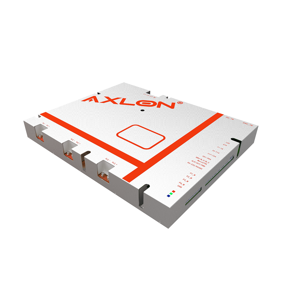
9. Product specifications and pictures
9.1 Product Specifications
Length * width * height :526*337*68mm
Length (mm) | Width (mm) | Height (mm) |
526 | 337 | 68 |
9.2 Product Pictures

10. Warranty and after-sales service
10.1 Quality assurance The warranty period is 1 year.
11.2 Electrical schematic diagram for multi-level power supply parallel application (AC220/DC24V dual power supply) When controlling the AC220V contactor coil:

When controlling the DC24V contactor coil:

When multiple power systems are connected in parallel to achieve power expansion, it is recommended to use power system M as the control center to connect and expand power systems T and B.
11.3 Wiring and sequence diagram of multi machine power supply parallel system