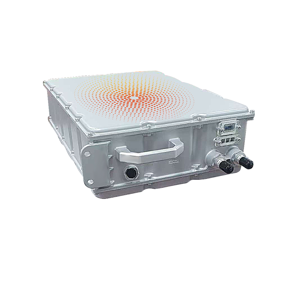
This product is a DC continuous wired dual-mode communication version of the charging pile, is a high-performance DC charging pile independently developed by Jiangsu Esilang Electric Co., LTD., with the characteristics of simple operation, high stability, high reliability, the power system can be multiple groups of parallel, to achieve power expansion to meet higher power requirements, but also has the characteristics of wired communication, wireless communication redundancy. It has specific control, display and communication functions to convert AC energy into DC energy and transmit it to the charging facilities of new energy electric vehicles.
Technical parameter
Model number | FC200 | FC500 | FC640 |
Rated power | 200KW | 500KW | 640KW |
Display mode | 7 inch touch screen | ||
Networking mode | Choose between 4G and Ethernet | ||
Charging mode | Time mode, power mode, amount mode, automatic full, power mode, reservation mode | ||
Charging mode | RFID card, password charging, optional mobile scan code, optional VIN code | ||
Installation mode | split | ||
reveal | Host with display, terminal with display, swipe card | ||
Environmental parameter
Operating temperature (℃) | -20 ~ +50 |
Storage temperature (℃) | -40 to +70 |
Transport temperature (℃) | -40 to +70 |
Relative humidity | ≤ 95% |
Atmospheric pressure (kPa) | 70 ~ 106 |
altitude | ≤2000m |
Waterproof class | IP54 |
Equipment cooling system | Forced air cooling, dust-proof design |
Acoustic noise (dB) | ≤65db |
Class of protection | PCB board, connectors and other circuits should be anti-damp, anti-mildew, anti-salt spray treatment, among which the anti-salt spray corrosion capability meets the requirements of Table 9 in GB/T 4797.6-1995, so that the charge and discharge device can operate normally in the outdoor humid environment containing salt spray. |
Other parameters
Installation mode | split |
Pilot lamp | Red light: When the charging pile is energized, the red light is on as a power indicator. Green light: when the charging pile is charging, the green light is steady on, and when the charging pile is inserting the gun, the green light flashes. Yellow light: The yellow light is off during normal operation, and the yellow light is on when there is a fault. |
BMS voltage selection | Switching between 12V, 24V, and 12V/24V |
Hot swap requirements | The rectifier module meets the requirements for hot swap |
Failure isolation | After the rectifier module fails, it can disconnect from the system reliably |
Packing and transportation | Three level highway 3000 km |
Environmental protection requirement | Rohs6 |
Mean time without failure | MTBF≥8868h |
Input characteristic
Model number | FC200 | FC500 | FC640 |
Input voltage | 380V ac±15% (three-phase 5-wire) | ||
Ac input frequency | 45~65Hz | ||
Maximum efficiency | 0.95 or higher | ||
Power factor | > 0.99 | ||
Input total harmonic content | < 5% | ||
Output characteristic
Model number | FC200 | FC500 | FC640 |
Output voltage range | 150-1000V dc | ||
Maximum output power | 200KW@300~1000Vdc | 500KW@300~1000Vdc | 640KW@300~1000Vdc |
Output interface | GBT 20234.3/CCS COMBO 1/2 | ||
Support protocol | CAN Bus (SAEJ1939) | ||
Charging time | 12 min | 8 min | 5 min |
Protective characteristic
Output short-circuit protection | No output after protection, unrecoverable (manual recovery required) |
Output overvoltage protection | After protection, there is no output and can be restored |
Output undervoltage protection | After protection, there is no output and can be restored |
Input overvoltage protection | After protection, there is no output and can be restored |
Input undervoltage protection | After protection, there is no output and can be restored |
Ac phase loss protection | After protection, there is no output and can be restored |
Overtemperature protection | After protection, there is no output and can be restored |
Safety characteristic
Withstand voltage test voltage (input-chassis) | 2000Vac 1min 10mA |
Withstand voltage test voltage (output - chassis) | 2000Vac 1min 10mA |
Input to chassis insulation (DC500V) | ≥10MΩ (atmospheric relative humidity 90%, no condensation) |
Output insulation to chassis (DC500V) | ≥10MΩ (atmospheric relative humidity 90%, no condensation) |
Radiation sensitivity RS | 80M~1GHz 10V/m,80% AM |
Conducted immunity CS | 150KHz~80MHz 10V, 80% AM |
Electrical fast transient pulse group EFT | ±2KV |
Technical standards and regulations
Communication protocol execution standards | GB/T 27930-2015 Communication protocol between electric vehicle non-on-board conduction chargers and battery management systems |
Charging piles perform standard | GB/T 20234.1-2015 Connection devices for conductive charging of electric vehicles - Part 1: General requirements GB/T 20234.3-2015 Connection devices for conductive charging of electric vehicles - Part 3: DC charging interface GB/T 18487.1-2015 Conduction charging systems for electric vehicles - Part 1: General requirements NB/T 33001-2010 Electric vehicle non-on-board conduction charger technical conditions NB/T 33008.1-2013 Electric vehicle charging equipment inspection test specification Part 1 non-vehicle charger NB/T 33008.3-2013 Electric vehicle charging equipment inspection test specification Part 3 DC charging pile IEC 61000-4-5 1999 Electromagnetic Compatibility testing and measurement techniques Surge (shock) immunity test Q/GDW1235-2014 Electric vehicle non-on-board charger communication protocol Q/GDW1591-2014 Electric vehicle non-on-board charger inspection technical specification Q/GDW 1233.1-2014 General requirements for non-on-board chargers for electric vehicles Q/GDW 1234.1-2014 Specification for charging interfaces for electric vehicles Part 1: General requirements Q/GDW 1591-2014 Technical Specification for the inspection of non-on-board electric vehicle chargers Q/GDW 1235-2014 Non-on-board charger Communication protocol for electric vehicles GB/T2423-2008 Environmental test for electrical and electronic products GB 4208-2008 Enclosure Protection Class (IP code) GB/T 19826-2005 General technical conditions and safety requirements for DC power supply equipment in power engineering GB/T 17626.2-2006 Electromagnetic compatibility test and measurement techniques Electrostatic discharge immunity test GB/T 17626.3-2006 Electromagnetic compatibility test and measurement techniques radiofrequency electromagnetic field radiation immunity test GB/T 17626.4-2006 Electromagnetic compatibility test and measurement techniques Electrical fast transient pulse group immunity GB/T 17626.5-2006 Electromagnetic compatibility test and measurement technology Surge (shock) immunity test GB/T 17626.11-2006 Electromagnetic compatibility test and measurement techniques Immunity test for voltage dips, short interruptions and voltage changes |